How to Use Dial Indicators and Calipers
Precision measurement tools are indispensable for woodturners. A dial indicator helps you check your lathe for spindle runout, while calipers let you measure bowl wall thickness, tenon diameters, and mortise depths accurately. These two tools will help keep the machines you depend on running at peak performance.
When used either alone or together, a dial indicator and dial caliper are extremely versatile tools capable of dozens of precise measuring jobs in the woodshop. They are useful when making delicate adjustments to machinery and jigs, such as squaring up a drill press table to the bit, setting the height of a shaper cutter, or adjusting a fence on a router table.
Further, a dial indicator is in dispensable for diagnosing machinery problems, such as warped sawblades or bent arbors-necessary evaluations when buying or repairing used machinery as well. Dial indicators and calipers also earn their keep when directly measuring wood and wooden parts: checking the thickness of a freshly planed board, determining a dowel's actual diameter, or laying out mortises and tenons.
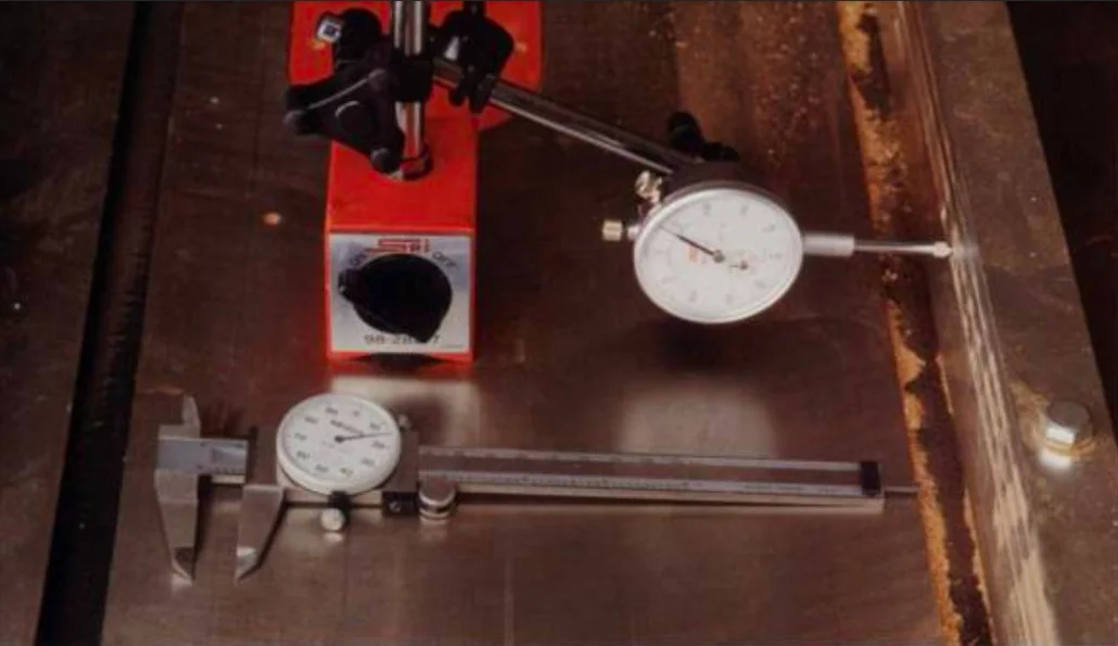 A dial indicator (top) and a dial caliper (bottom) are precise machinist's tools that are very handy in the woodworking shop for jobs like setting up equipment and jigs, troubleshooting problems, such as cutter vibration, and measuring wooden parts.
When used together, the dial indicator and caliper complement each oth er; after precise adjustments to a machine setup are made with the dial indicator, you can use the caliper to check the effect, by measuring a test piece cut on the machine.
It takes a bit of effort to learn how to use these devices, but no more than what is required to operate a new microwave oven or car stereo.
Here I'll tell you how I choose and use dial indicators and calipers in my woodworking shop, including which types to buy (and where to find them), how they operate and how to set them up. And I'll present more than a dozen different applications, to give you some ideas for using them in your own shop.
Dial Indicator and Caliper Anatomy
Dial Indicator and Caliper Anatomy on AmazonDial indicators, dial calipers, and their accessories are built to exacting standards and are typically capable of measuring minute differences within a few thousandths of an inch. At the heart of both tools is a small gauge, with a watch like a needle that shows readings on a calibrated dial.
On both tools, the dial is movable so it can be set to zero, regardless of needle position. While these tools come in many sizes and dial configurations, increments on most are 0.001 in., with one revolution of the needle equaling 1/10 in. A secondary dial on some dial indicators shows how many times around the needle has traveled.
The needle on a dial indicator gauge is connected to a spring loaded plunger that moves in and out, turtling the needle via a rack-and-pinion gearing system. Most plungers accept screw-on re movable tips, which are available in a variety of styles for different applications.
The gauge attaches to a set of adjustable arms that allow the indicator to be positioned over or beside the measured part. The arms mount to a special base with an on/off switch that controls the strong magnets inside, which is used to clamp the tool to a metal surface. The dial indicator is meant to be held stationary by the magnetic base while the part you wish to measure presses against the tip of the indicator's plunger.
Before taking a measurement, the indicator's rotating dial should always be turned until the needle reads zero. Now any variation in the measured surface as the part is rotated or moved past the indicator's tip will be displayed in thousandths of an inch by the needle on the dial.
Anytime Tools Dial Indicator Set with Magnetic Base on AmazonLike the dial indicator, the needle on the dial caliper's gauge is actuated by rack-and-pinion gearing and reads the motion of two sets of jaws designed to take inside or outside measurements. As the jaws open, a rod slides out the bottom of the tool, for measuring the depth of holes and recesses. Most dial calipers have a small thumb wheel for adjustments and a knob to lock a measurement in place.
Both of these precision instruments need to be treated with care and should be stored in a covered box when not in use. Wood chips and dust can clog the gears on a dial caliper or the plunger on the dial caliper; a small paint brush is handy for sweeping away dust.
Which Dial and Caliper to Buy
We have a dedicated post about choosing a digital caliper.
Often, good-quality used dial indicators and calipers are avail able at pawn shops. But check them before buying: Push the dial indicator's shaft in and out and make sure the needle returns precisely to the same spot each time. If it returns slowly or roughly, particularly when the indicator is upside down, the plunger shaft is probably distorted or bent. If you notice this problem, never squirt oil or WD-40 into the works; it wreaks havoc with delicate working parts. When buying a used dial caliper, check the jaws for dings or alignment problems, and make sure they operate smoothly.
Principles of Use for Dials and Calipers
As versatile as dial indicators and calipers can be, they're like a set of encyclopedias-they must be used to be of any real value. When using the dial indicator on machinery, there are a few general rules to follow. Most importantly, you must un plug the machine before beginning work and never use the dial indicator to read a shaft or surface that's turning under power!
Fix the indicator's base to the machine's metal table or frame or, if you're working on a wooden jig, clamp the base in place. Then position the plunger tip against the part and perpendicular to (or parallel, as in the case of setting shaper knife height) the surface or shaft in the direction you want to measure.
For example, to check the runout (the amount that a shaft or disc is out of round) of a sawblade, the plunger is placed perpendicular to the flat body of the blade. On narrow surfaces, such as the side of a thin shaft, a large, flat accessory tip screwed to the plunger makes it easier to get a true reading.
When turning a shaft, pulley, etc., to take a measurement, isolate the turning force as far from the part being read by the indicator as possible. For example, when checking spindle runout on a drill press, turn the motor pulley rather than the spindle, because hand turning can deflect the spindle and give a false reading.
When measuring thin or delicate items, put as little indicator plunger pressure as possible against the surface being measured, to avoid de flection from the plunger spring. Also, examine the surface being checked for large dips, protruSions, burrs, or rough spots. These defects can make the indicator show more runout than there is. Getting accurate readings from a dial caliper takes a bit of finesse.
When measuring the outside of a shaft, drill bit, etc., the caliper's jaws should be positioned at a right angle to the shaft. Apply just enough pressure to close the jaws, especially when checking wooden parts; some woods compress rather easily. Also, wood movement from humidity changes can affect the thickness of a part in one area more than another; several measurements should be taken and averaged, for accuracy.
Measuring inside dimensions requires the same technique except on holes with less than 1/4 in. ID. The narrow flats on the edges of the caliper's inside measuring jaws cause the indicator to read slightly undersize.
Applications for Dials and Calipers
You'll find there are literally hundreds of uses for dial indicators and dial calipers around a woodworking shop, but here I'll describe just some of those typical in a cabinet-making or furniture-making studio. Experiment and you'll come up with your own favorite applications.
General Machinery Setup
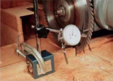 A dial indicator will quickly tell you the sawblade runout in thousandths of an inch. After making sure the arbor is true, the indicator's base is clamped to the radial-arm saw table and then the indicator reads wobble in the surface of the saw blade.
Checking adjustment accuracy
Most machines have handwheel cranks for setting the height or angle of blades and cutters. You can use the dial indicator to determine how much movement occurs in one crank of the handwheel so you can eyeball fine adjustments quickly.
Simply set the dial indicator tip against the machine's arbor or spindle, crank the wheel once, and read the amount of movement. Then repeat this to be sure. You can divide this measurement by four or eight and put tape marks on the handwheel every 90° or 45°, for making even finer adjustments quickly.
Checking an out-of-round pulley
Machine rumble and vibration is often caused by an out-of-round pulley, and with the tip of the indicator against the side of the pulley, you can check the pulley's trueness. If the rumble seems to be in sync with the revolutions of the belt, check by putting the indicator tip against either of the inside surfaces of the V-belt groove.
Checking shaft or arbor runout
After attaching the magnetic base to the machine's table or frame, set the indicator's tip perpendicular to and against a smooth part of the shaft. Watch the needle as the shaft rotates and read the amount of runout on the dial. On threaded shafts, slip a flat sleeve over the threads, to prevent the reading from being affected by the grooves.
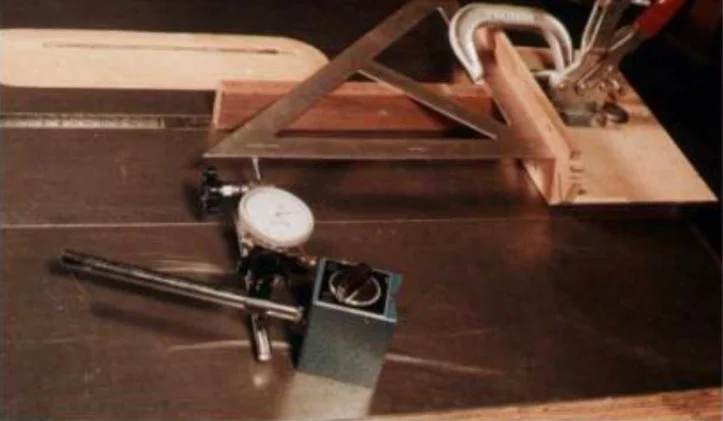 To set the table saw miter gauge at a perfect right angle to the blade, a steel draftsman's square is clamped to the head of the gauge and the indicator bears against the square as the gauge is slid along in the miter slot. Any change in a reading indicates that the gauge head is not exactly square and needs adjustment.
Checking for warped sawblades
Put the tip of the indicator against a smooth body of a blade and turn the spindle by pulling on the V-belt or, on a radial-arm saw, by turning the arbor itself. Mark any high spots with a pencil, rotate the blade 180° on the arbor, lock it on and check again. If the readings for the two blade positions differ, check the saw arbor's runout, as described above.
Table Saw
Checking the miter slot for parallel to the blade
Clamp the dial indicator's magnetic base to the head of the miter gauge; most heads are non-ferrous cast alloy, and so the magnet won't work. After raising the sawblade fully, set the indicator's tip against the face of the blade. Now slide the miter gauge back and forth and watch the readings.
Repeat this operation with the blade in several positions, in case the blade is warped. Adjust the saw table on its frame as necessary until the indicator reads zero or a minor variation.
See our guide to woodturning tools for more on equipping your shop.
Squaring the miter gauge head
Clamp an accurate draftsman's steel triangle (or a try square) to the saw's miter gauge, elevating it an inch or two above the saw table with a scrap of wood.
Fix the indicator's base to the table and set the indica tor's tip against one side of the triangle. Now slide the miter gauge back and forth and take a reading; adjust the angle of the head until mere is minimal or no variation showing on me indicator.
Setting the rip fence parallel to the miter slot
With the dial indicator clamped to the miter gauge as described earlier, place the indicator's tip against the rip fence and, with the fence locked, slide the miter gauge back and forth.
Adjust the fence so that its back end reads a few thousandths of an inch farther away than at the front end. Any roughness on the surface of the fence may cause the reading to undulate a bit; so use your best judgment.
Shaper
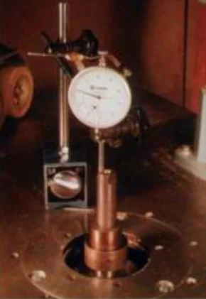 The amount a shaper cutter is raised and lowered can be accurately gauged by setting up the dial indicator with the tip against the top of the spindle, as shown. After raising or lowering the spindle to the desired amount, take a cut and use a dial caliper to check the results on the workpiece.
Setting up shaped cutters
For precise cutter-height adjustment, place your dial indicator's plunger parallel to the spindle so that the tip is against the top of the spindle (see the above photo at right). Then, raise or lower the spindle until you've reached me de sired setting, take a cut and use the dial caliper to check the work piece. If the cut is about 0.007 in. below where you want it, use the dial indicator to confirm that it is raised by the exact amount. The precision fit I get using this method when setting cope-and-stick or glue-joint cutters makes the purchase of these two tools worthwhile.
Checking spindle squareness to table
After checking for spindle runout, as described earlier, check for spindle squareness by attaching the base directly to the spindle, using the base's V-groove if it has one. Now sweep the indicator around the table; if the needle shows variations from one side to another, the table is out of square.
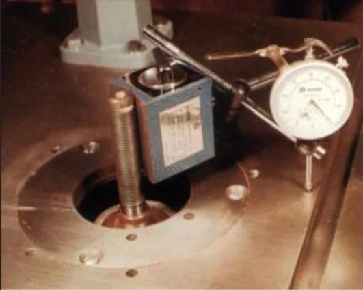 By attaching the dial indicator's magnetic base directly to the shaper spindle, you can check the squareness of the spindle to the table. Closely watch the dial as the indicator sweeps the table; any change in the dial reading indicates that the spindle is out of square with the table.
Drill Press
Checking for runout
You can check the runout of your drill press chuck and quill by attaching the magnetic base to the column and putting the dial indicator's tip against the smooth surface of the chuck or against the shank of a chucked bit or rod.
Squaring the drill press table
Do this just as described for the shaper, only attach the magnetic base directly to the chuck, or re move the indicator'S mounting arm from the base and mount it directly in the chuck and set the indicator tip against the table.
Sizing drill bits
This is an easy job for a dial caliper. If you don't have a caliper, you can use a dial indicator by attaching the base to your saw or jointer table, so that the tip is against the surface, and rolling the drill bit underneath to check its diameter. Use a conversion chart to change decimals into fractions.
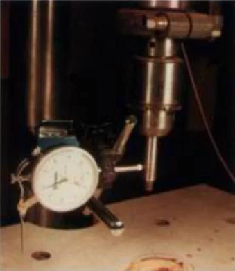 To check a drill press chuck for concentricity, attach the dial indicator's base to the column and set the indicator's tip against a chucked drill bit or rod. Any change in a reading indicates a runout.
Radial-arm Saw
General setup
The dial indicator is very useful in performing the numerous adjustments necessary to make a radial-arm saw cut precisely. For instance, to check the saw's squareness of cut, first remove the dial indicator's arm from its base and clamp the arm between the arbor flanges that normally secure the saw blade. Lev el the indicator's plunger and place the tip against one leg of a framing square while you hold the other leg firmly against the saw fence. ow pull the saw carriage down the arm and watch the reading; adjust the radial arm until there's little or no variation.
Router
Setting up router operations
Dial calipers are particularly handy when working with router jigs and setups. For example, you can easily check the diameter of a router bit wid1 the caliper's out side jaws and just as easily check the width of a groove with the inside jaws. You can also use the caliper's rod for measuring the depth of the groove. Use the dial indicator to check router bits, the collet, and the arbor for runout or for accurately setting a fence on your router table for cutting box joints, sliding dovetails, etc.
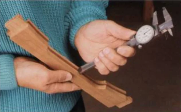 A dial caliper has special jaws for making several kinds of precise measurements, including a rod that slides out the bottom of the tool for checking the depth of a groove in a frame member.
Jointer and Planer
Setting jointer knives
With the base's magnet off and placed on the outfeed table, lock the dial indicator's arms so that the tip, fitted with a flat tip, touches the table. Zero the indicator's dial and then rotate the jointer's cutter head so that one of the knives is top dead center. Slide the indicator's tip over the knife and move it along its length; the dial should read zero across each knife. Using this method, you can also check if the cutter head is parallel to the outfeed table.
Setting up and using a planer
A dial indicator, fitted with a special base, is very useful for setting the planer's knives, as well as bed-roller height. You can use the dial caliper's outside measuring jaws to check the thickness of stock before or after it's run through a thickness planer.
Joinery
Making dowel joints
Standard-size dowels aren't always exact in diameter. Check the dowel diameter with the dial caliper; rotating the dowel while measuring will tell you if it's out of round as well. Use the caliper's inside-measuring jaws to size the hole produced by your drill bit and doweling jig before glue-up, to avoid a too-tight or too-loose joint.
Mortise-and-tenon joinery
Just as with checking dowel diameter, you should use the dial caliper to check your tenons for prop er thickness, shoulder size, and depth, and to check the mortises for proper size and depth, all of which will produce a stronger joint and make glue-up a lot easier. You can also use the dial indicator to set the fence for either tenon cutting or mortising; the dial will show you how far the fence is moved in or out, so you can make an adjustment within a few thousandths of an inch needed for a perfect fit.
We are proud to host this tutorial with permission from Bob Vaughan.
Written by Vince
Vince is a woodturner and the founder of WoodturningOnline. He writes tool reviews, buying guides, and turning tutorials to help woodturners at every level make informed decisions about their craft and equipment.