Making Your Own Hollowing Rig
If you would like to experiment with hollowing or deep boring but are reluctant to make a large investment beforehand, this hollowing rig may be the project for you to try. It works very well and can be made for well under $100 (plus sweat equity), including laser. A commercially made rig like the Jamieson or Hunter can run $300 to $500 more, and may not be as flexible in use.
You will need an electric drill (preferably variable speed), and access to a band saw and a workbench with a vise. All required hardware is available from a full-line hardware store such as Ace hardware. Needed materials, drills, tap wrench, and tap are listed on the appended parts lists.
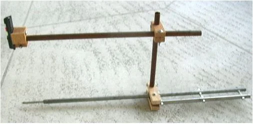 Laser Attachment Mounted on Outrigger
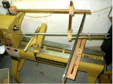 Hollowing Rig Assembled on Lathe
History
The original basis for this design originated in an article in the Fall 2001 issue of American Woodturner entitled “Trapped Boring Bars” by Steve Sinner. He felt that there were limitations in movement due to the large space between elements in the stabilizer unit, or outrigger, of the commercial units available. He simply welded two bars together. Member Allen Quandee made a modified version of that design, fastening the bars together with hardware instead, and securing the support structure to the lathe bed differently. It worked very satisfactorily and is still in use today. The details shown in this article use other hardware than Allen did for the bars, but the rest is essentially the same as his. A laser attachment has been added.
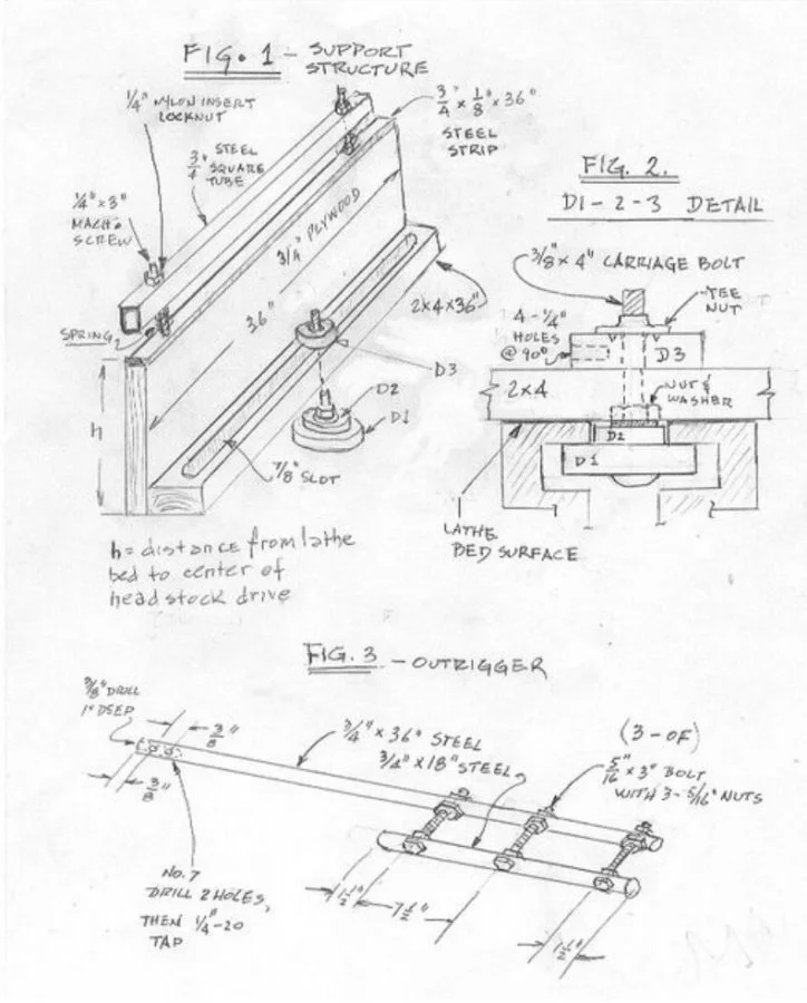
Support Structure
(See Figures 1 and 2) The support structure acts as a secondary tool rest and has a restraining bar to counteract the twisting reaction force on the cutter end and thus keeps the outrigger and cutter level. The turner only has to be concerned with moving the cutter into the piece, requiring little effort. The upright is ¾” plywood, with a top facing of ¾” x 1/8” steel strip. A 5/16” hole is drilled 1 inch from either end of both the steel strip and the ¾” x ¾” square steel tube. Mark locations with a set point punch. The strip is glued to the plywood with epoxy or Goop adhesive (I used Goop). Drill a ¼” hole 1” deep into the plywood at the locations of the holes in the metal pieces. Cut the heads off two 3” long ¼” machine screws with a hacksaw and secure them into the holes with epoxy adhesive. After it has set, slip the two small springs over the upright bolts, insert the bar, and secure with two ¼” nylon insert nuts.
The 2”x 4” lumber slide bar at the bottom is prepared as follows: Draw one line lengthwise along the center of the piece. Draw two parallel lines, one on either side of that, each 7/16” from the center. Drill 7/8” holes 2 inches from each end at the centerline. With the bandsaw, cut the piece in two along the centerline. Saw out a half slot on each piece along the lines you have previously drawn. Reassemble by applying the carpenter’s glue to the ends and clamping for a half hour or more. After the glue has set, fasten the piece to the plywood upright with wood screws, four or so should suffice.
The support structure is secured to the lathe bed with an assembly composed of three discs, a 3/8” x 4” carriage bolt, a nut and washer, and a tee nut, as shown in Figure 2. The bottom two discs, D1 and D2 serve the same function as the steel piece to be found under the lathe bed on the tailstock and tool post (for your HSS or carbide tools). The diameters should be cut to accommodate the dimensions of your lathe bed. Disc D3 is 3” in diameter. D1 and D3 are ¾” plywood or hardwood; D2 is ½” plywood or hardwood. Scribe the disc diameters on your wood with a compass and cut out on the bandsaw. Drill a 3/8” hole in the center of each. Hammer the tee nut into D3 as shown, and drill four ¼” holes at 90-degree intervals in the side, so that you can tighten up by inserting a ¼” dowel or steel bar. Assemble as shown.
Outrigger Bar
(Figure 3) The outrigger consists of two ¾” steel bars, 36” and 18” long, fastened together by 5/16” x3 “ bolts. The long end is drilled 3/8” x 1” deep to accept the tool bits, which are held in place by two ¼”- 20 x ½” set screws. The drills you use should be of good quality for metalwork. If you choose to buy cobalt steel heavy-duty drills, the work will go even more easily, (Available from ENCO, www.use-enco.com). Lubricate the hole with plenty of oil while drilling, and back chips out. Locate the holes with a set point punch, and start each hole with a small drill, as a precaution to prevent the larger tip from slipping off the mark.
To ensure hole alignment when the bars are bolted together, clamp both bars together horizontally tightly in a bench vise, and drill all the holes through both bars together. For the 5/16” bolts, use an 11/32 drill, and drill 1 down as close to vertical as you can manage. Next, remove, and clamp the longer bar vertically and drill a 3/8” hole 1 inch deep in the end. Now clamp the bar horizontally and drill two holes with a No. 7 drill (or a 13/64” drill if you don’t have a No.7), at the spacing shown. With your ¼” x 20 taps inserted in your tap wrench, tap the two holes you have just drilled. Use oil, go slowly, and back off every turn or so to remove chips.
Assemble as in the diagram, and you are done.
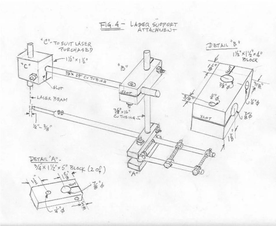
Laser Support Attachment
(Figure 4) By use of a laser as a thickness guide, one can attain a more uniform wall thickness. For starters, the laser dot should be set no closer than ¼” - 3/8” from the contact area on the cutter to avoid errors that could cause you to cut through the wall. The support attachment is made of a 7/8” outside diameter thin wall copper tubing lengths fastened to the Outrigger Bar by means of wooden blocks clamped to the area near the end of the smaller bar with a through bolt. The tubing is secured in 7/8” holes in the blocks which have a slot cut through on the bandsaw. At right angles to the slot, holes are drilled for through bolts. As the bolts are tightened, the slotted area flexes slightly, acting to clamp the tubing in place. The laser support block clamps onto the end of the horizontal tube in a similar manner. You will have to detail this block to suit the laser which you purchase. (The cylindrical type of laser pointer shown on the figure, available in office supply stores, usually has an “on” button which has to be held depressed for the laser to remain energized. I chose to use the top half of a miniature laser level because it had a push to energize and push to turn-off button, available at Harbor Freight Tool Co.)
The laser target point is adjusted by loosening the back-end support of the horizontal tube and sliding it in and out and rotating, then tightening.
The sketch and block details in Figure 4 should be sufficient for fabrication.
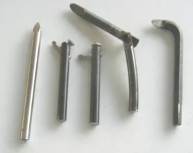
Tool Bits, Left to Right: 3/8” HSS Straight Bit, 3/8” Boring Bar with 3/16” HSS Bit, Ditto, 3/8” Drill Rod Adjustable Angle Bit (Source of Materials: ENCO), Ground Hex Wrench Bit.
See also: best steady rests for wood lathes.
Material Lists
Support Structure
Wood
- ¼ sheet of ¾ inch plywood cut 36” long.
- 2 small pieces of ¾ inch plywood or hardwood for discs D1 and D3
- 1 small piece of ½ inch plywood or hardwood for disc D2
Hardware
- 3/8” x 4” carriage bolt, 3/8” nut and washer, 3/8” tee nut (for disc assembly)
- ¾” x 1/8” steel bar 36” long
- ¾” x ¾” square steel tubing 36” long
- 2 ¼” x 3” machine screws, 2 !/4” nylon insert locknuts, 2 small springs 1 inch long, 4 ¼”
- washers for bar support assembly.
- 4 2” wood screws - for fastening 2x4 slide bar
Drills
- ¼, 5/16, 3/8, 7/8 wood bit
Other
- Adhesives: Epoxy and Goop (optional), setpoint punch, hack saw
Outrigger Bar
Hardware
- 1 ¾”x18” steel bar; 1 ¾”x 36” steel bar
- 3 5/16”x3” hex head bolts, 9 5/16” nuts - for bar spacers
- 2 ¼”–20 x ½” set screws
Drills
- No. 7 (or 13/64), 11/32, 3/8
Other
- Small tap wrench, ¼ -20 tap, setpoint punch
Laser Support Attachment
Wood
- ¾”x1 ½” hardwood, 1 ½”x 1 ½” hardwood - dimensions in Figure 4
Hardware
- 1 28” length of 7/8 O.D. copper tubing, 1 16” length of 7/8” O.D. copper tubing
- 5 ¼”x2” machine screws, 1 ¼”x2 ½” machine screw, 6 ¼” hex nuts, 12 ¼” washers
Drills
- ¼, 7/8 wood bit
Other
- Laser
Written by Vince
Vince is a woodturner and the founder of WoodturningOnline. He writes tool reviews, buying guides, and turning tutorials to help woodturners at every level make informed decisions about their craft and equipment.